Create Virtual Commissioning Models directly in the CAD Environment
Emulate3D's CAD Is The Model software technology is a unique PLC Controls Testing tool that allows users to create Virtual Commissioning Models directly in the CAD Environment. Globally recognised, the integration with existing CAD packages is what makes Emulate3D's CITM offering unique and so powerful.
CITM provides the link between a mechanical CAD design and the electronic process control of a PLC way back at the design phase. This provides a platform where controls testing can occur earlier and prior to any physical manufacturing.
Design your machine within your familiar CAD systemEmulation for Machine Builders technology is based on the “CAD is the model” concept which enables you to design your machine within your familiar CAD system. Emulate3D’s Add-in makes it straightforward to create a running controls testing model with your standard CAD control elements such as sensors, conveyors, pushers, and other mechanisms. |  |
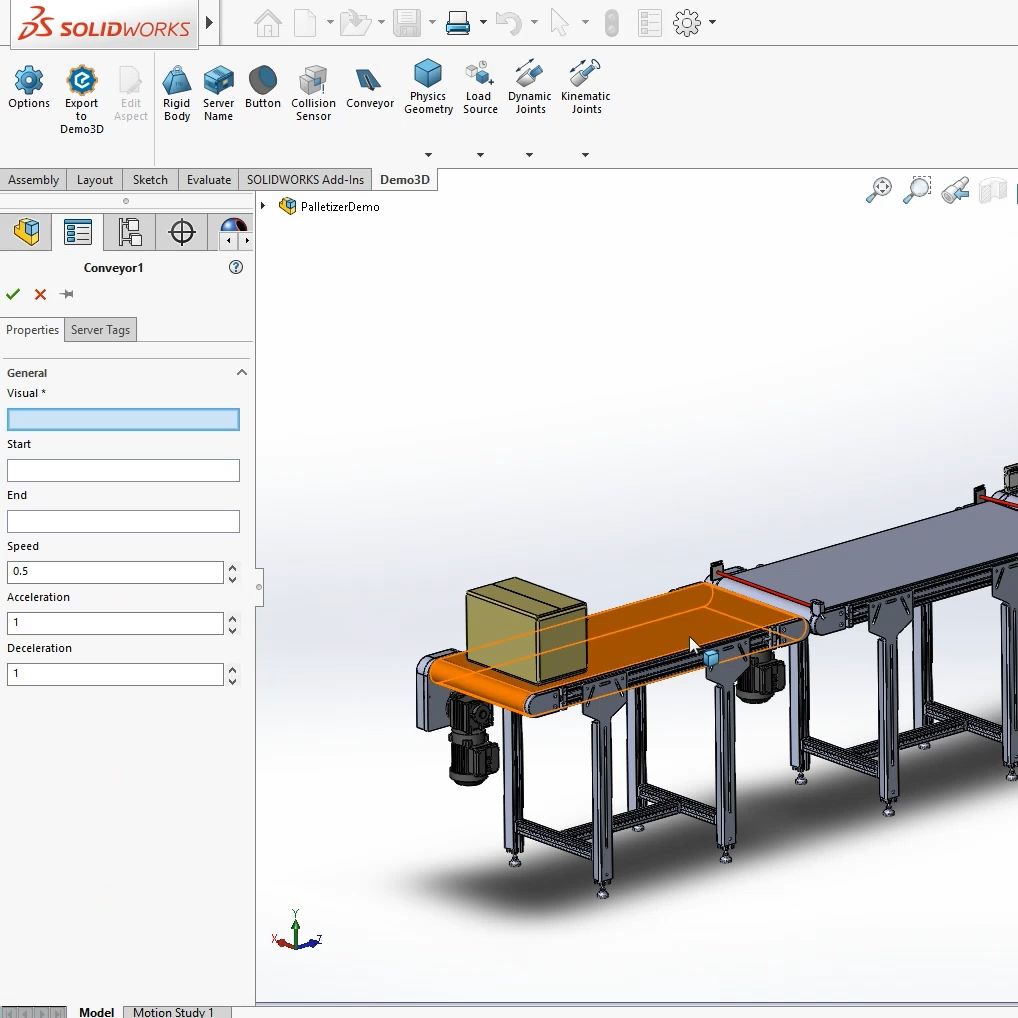 | Create a valuable testbed in the form of a Dynamic Digital TwinCAD Is The Model, commonly called Emulate3D for Machine Builders, helps users create controls testing models of a wide range of machine types, directly within your chosen CAD package. In fact CITM can be used for anything mechanical that may be automated! Debug and refine the kinematic sequences and timing of your designs in a virtual environment, and make changes to them faster than is possible with physical prototypes. Create your machine or mechanical system in CAD, mark up the various kinematic and control elements, then connect the control and activation elements to the PLC IO and run the emulation model. By combining mechanical CAD information with real control system logic you can create a valuable testbed in the form of a Dynamic Digital Twin |
Reduce your time to market
Emulate3D Controls Testing for Machine Builders software enables you to test out and debug your machine controls before the machine is built, by automatically connecting the PLC to your CAD model. Reduce your time to market and cut development costs by running logic tests and carrying out design changes on your machine’s digital twin in a safe virtual environment before building a physical prototype.
CAD is the Model is designed to be a process that fits easily with your existing workflow – it is additive rather than intrusive.
A CITM Controls Testing model can be built in 3 simple steps.
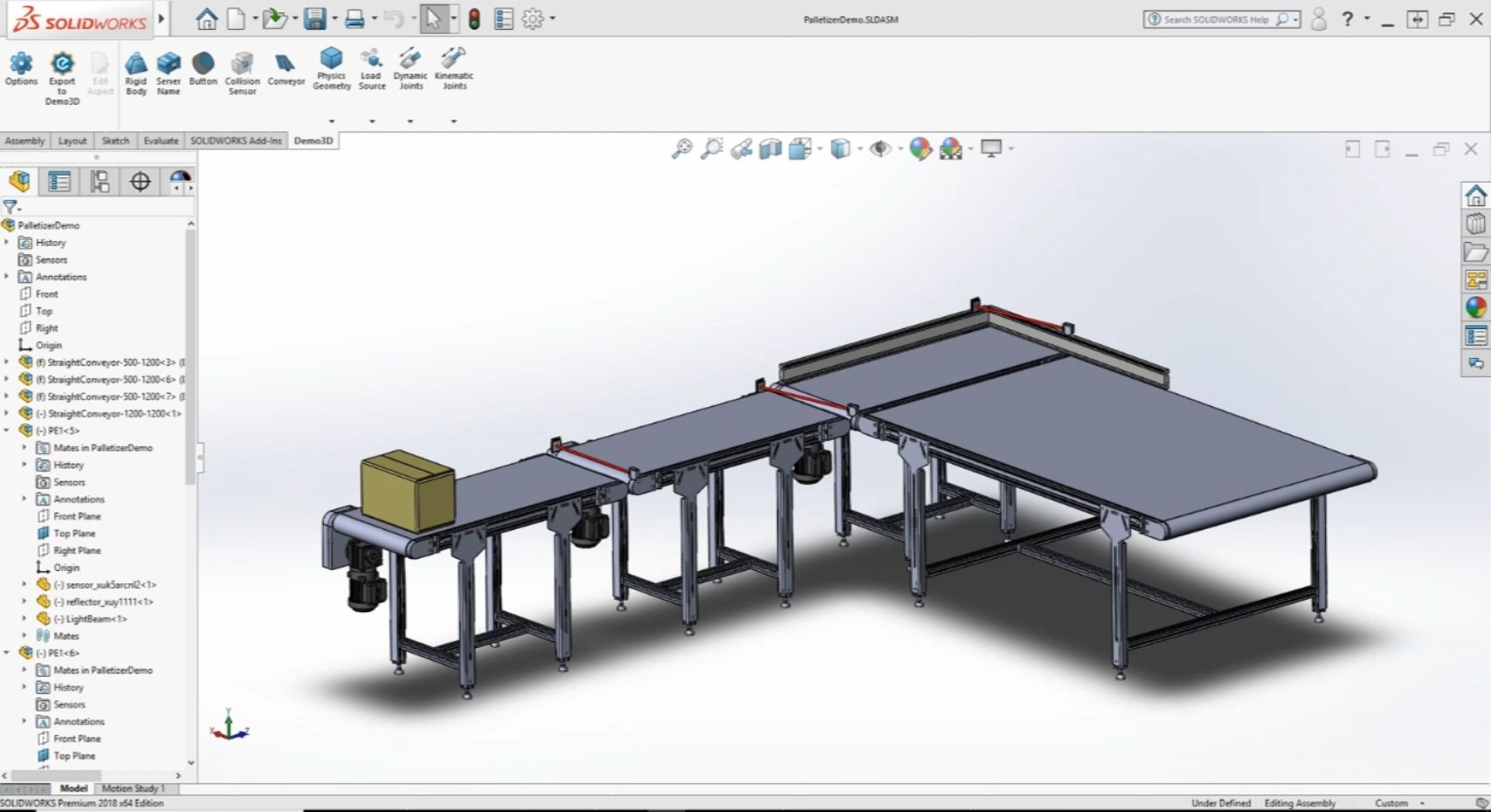 Step 1:Create your mechanical system in your chosen CAD package |
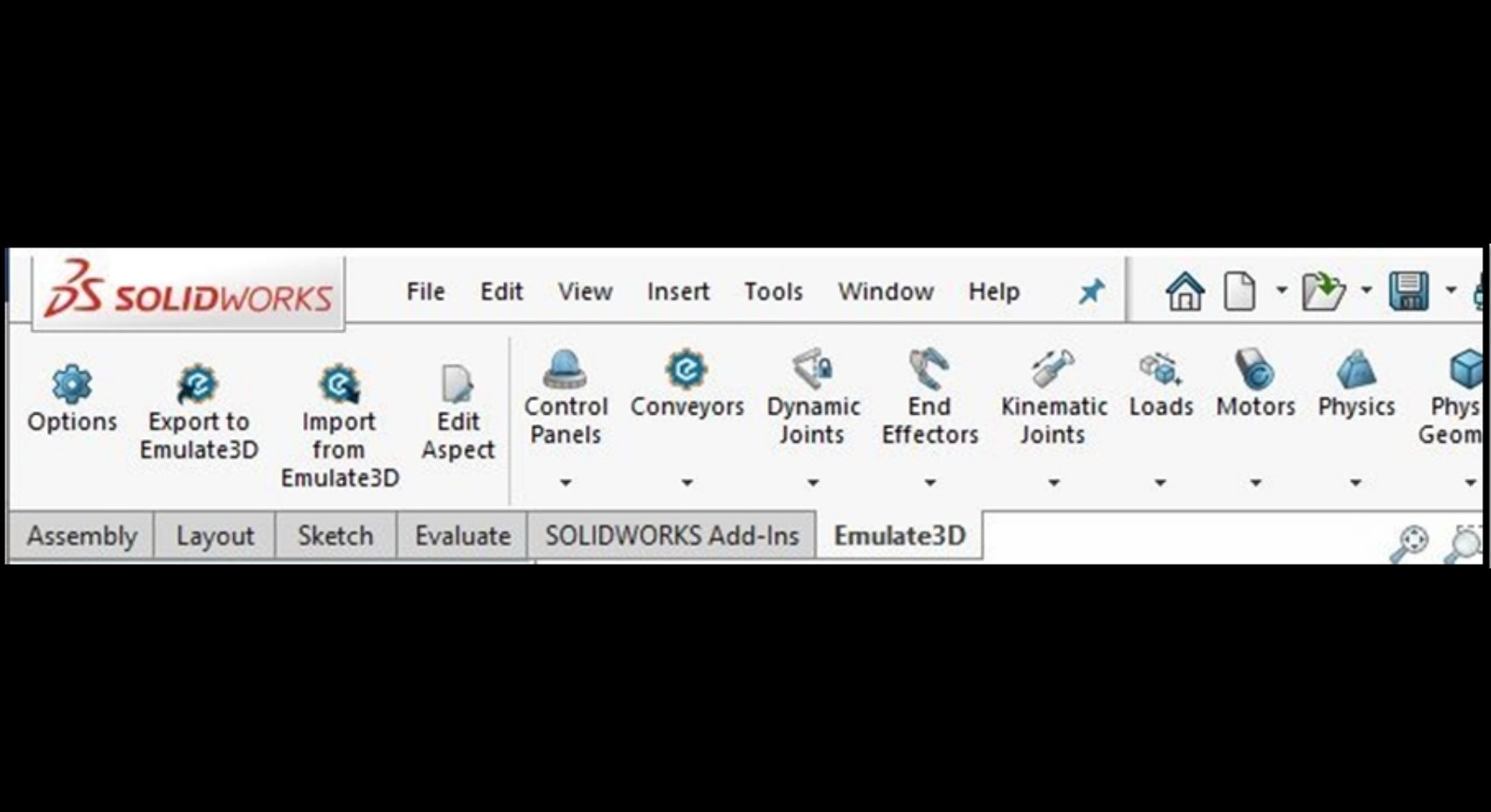 Step 2:Switch to the Emulate3D add-in ribbon and mark up your CAD using the ribbon elements created for your application. The process of marking up CAD elements enables them to be recognised automatically as control or activation elements in the Emulate3D runtime environment, and behave appropriately. |
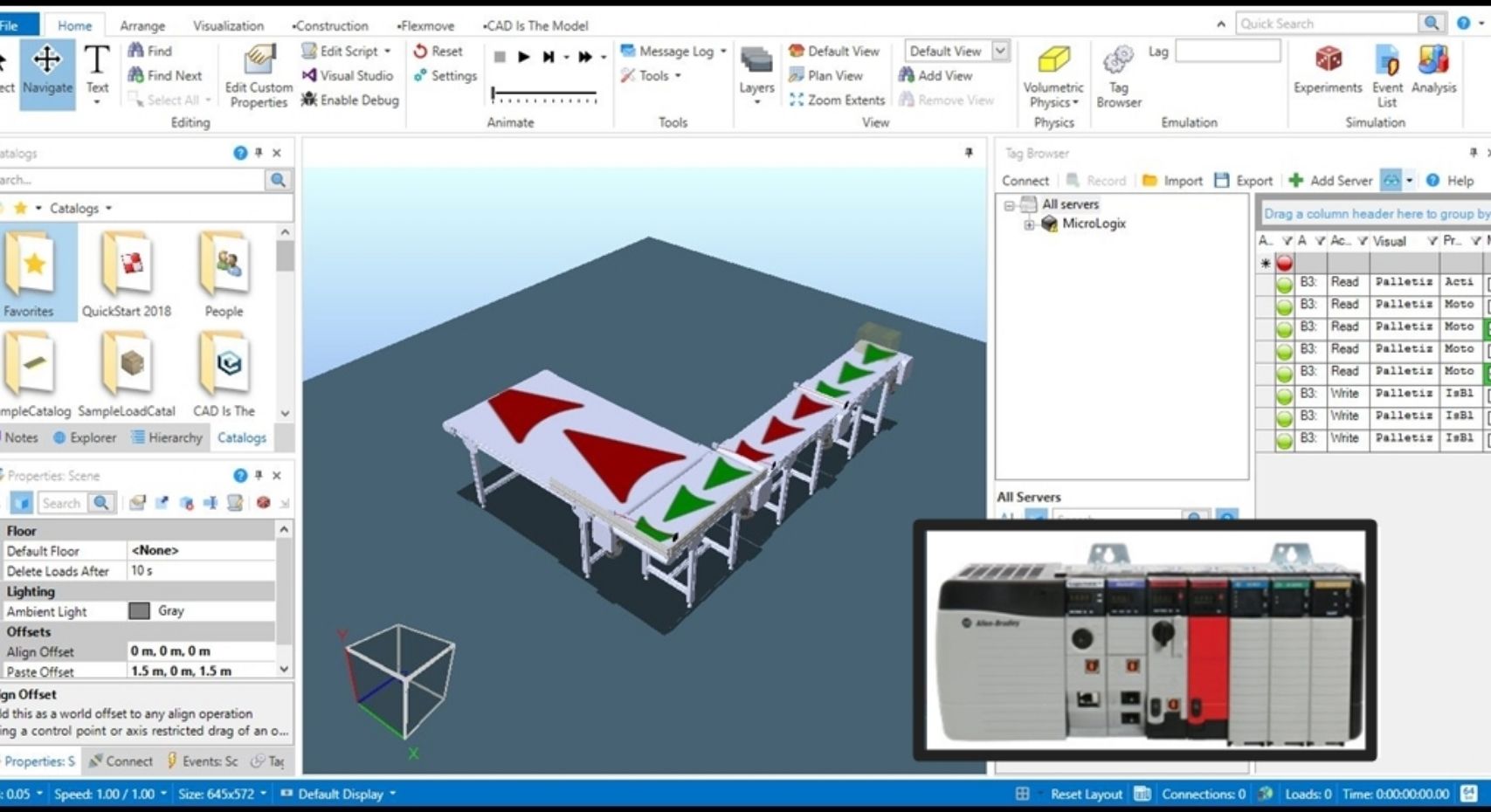 Step 3:Export to Emulate3D and connect directly to a PLC |
 | How can Emulate3D help you and how can it be implemented?
|
